We measured the base of the Einstein bust and found that it was 3" x 2.5" x 2.5". We defined our coordinate space as having one corner of the base as the origin, and alis-aligning the faces of the base. We now have a correspondence between six 2D pixel coordinates and six 3D points in reality.
Since we are looking for an orthographic camera matrix "C", we can simply solve for the 2x4 matrix that maps the real points using the pseudoinverse:
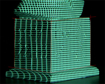
Now we choose some grid points on the two visible faces of the base. We call one point the origin of "projector space" and determine the location of the other points in "projector space" by counting the number of grid squares right and up from the origin. To find the 3D location of each of our selected grid points, we essentially warp the grid of each face into real-world coordinates, which is especially easy to do because we are assuming the camera is orthographic. We can now solve for the orthographic projector matrix in exactly the same way as we solved for the camera matrix. Only four points are necessary, but we used six for more accuracy:
Once you have the camera and projection matrices, you can do the reconstruction, as discussed in the next section...